Frame
Configuration
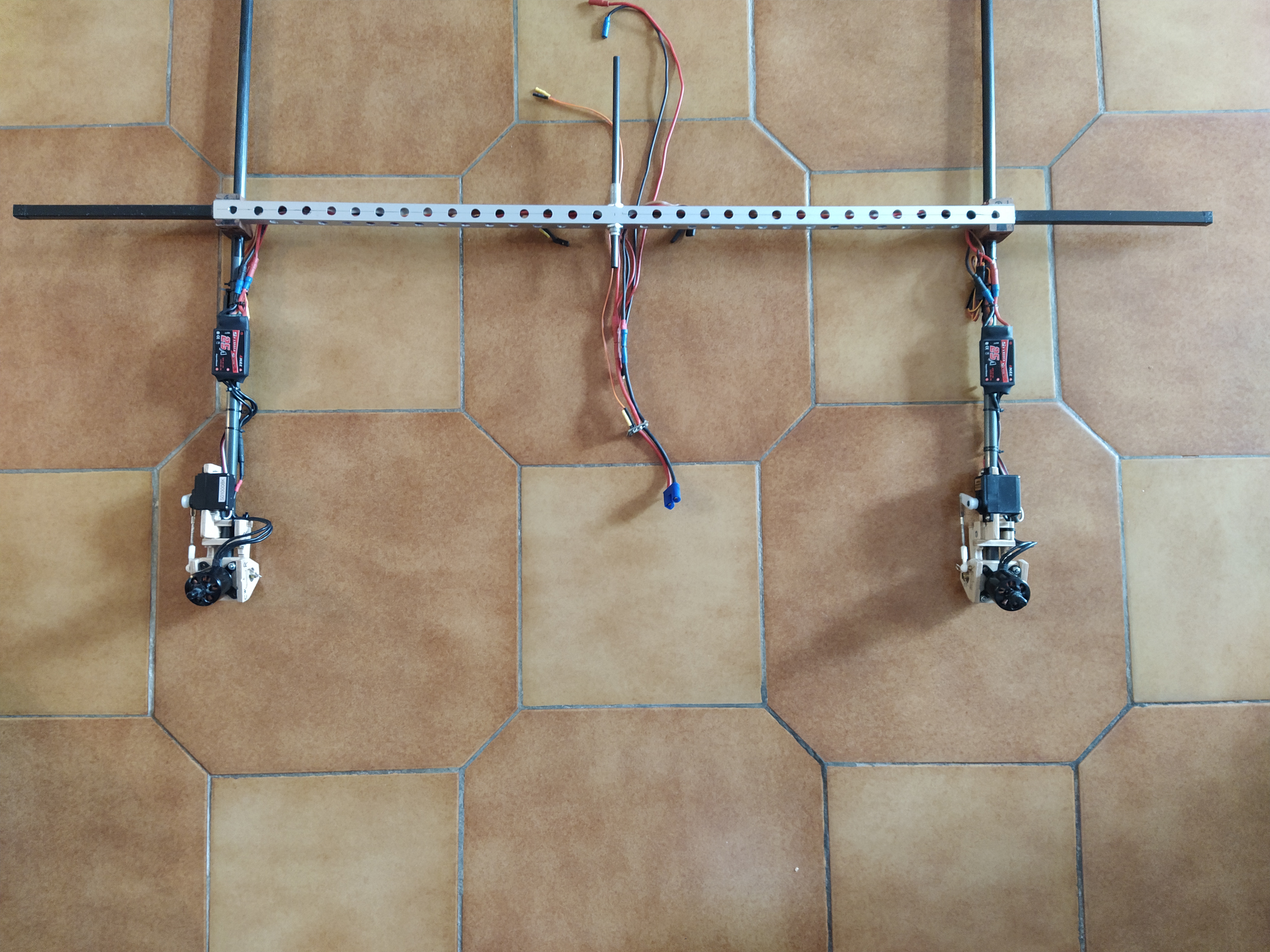
The chosen aircraft configuration is a tilt-rotor tricopter. It is based on a 1.8m span RC glider. A rearward motor is fixed on the fuselage in front of the rudder. The front motors can tilt around the pitch axis to ensure yaw control and forward flight propulsion. Controls include:
the three motor speed
the tilt angle of the two front motors
the elevator
the ailerons
which requires 7 PWM outputs.
Note
For simplicity, the rudder is fixed.
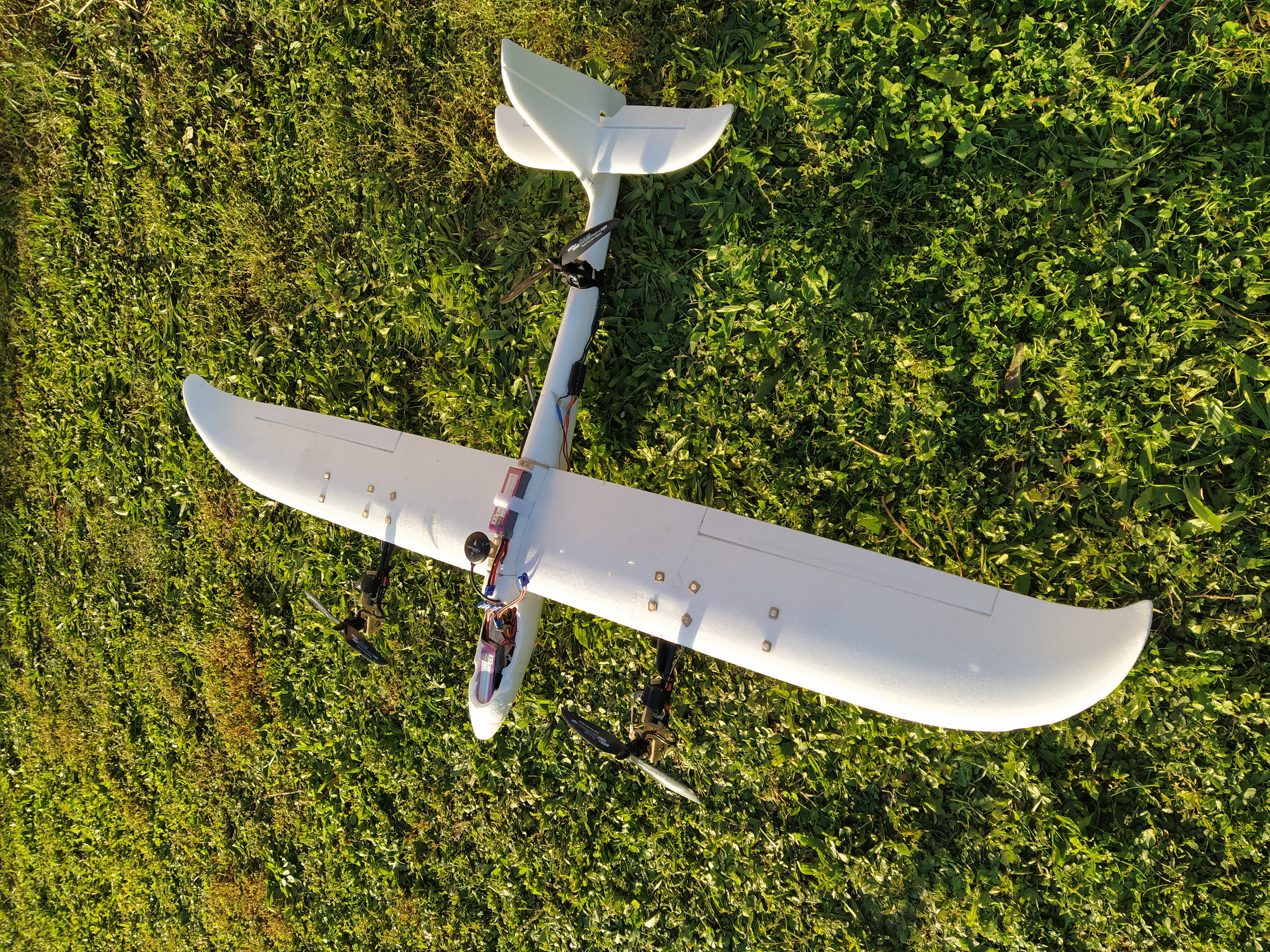
Fig. 1 Global view of the VTOL tricopter prototype.
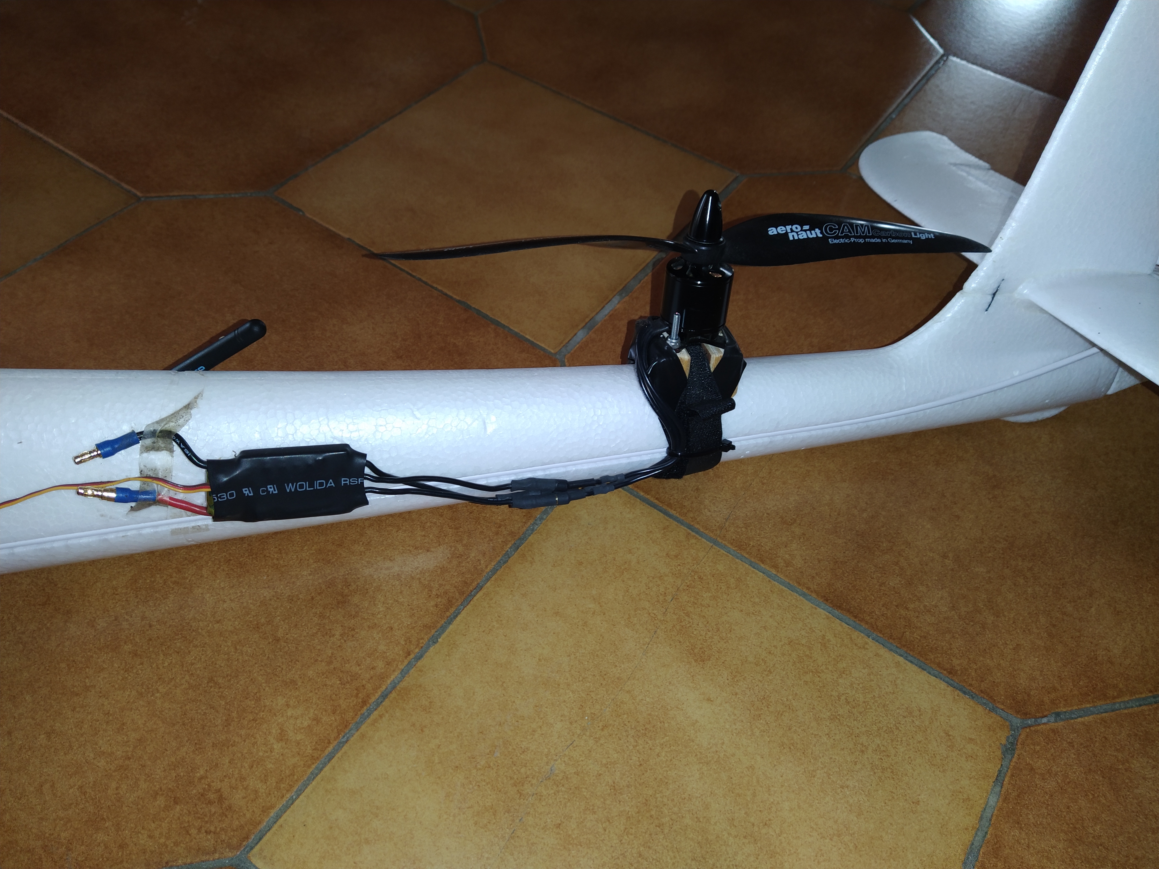
Fig. 2 Rear motor mounting.
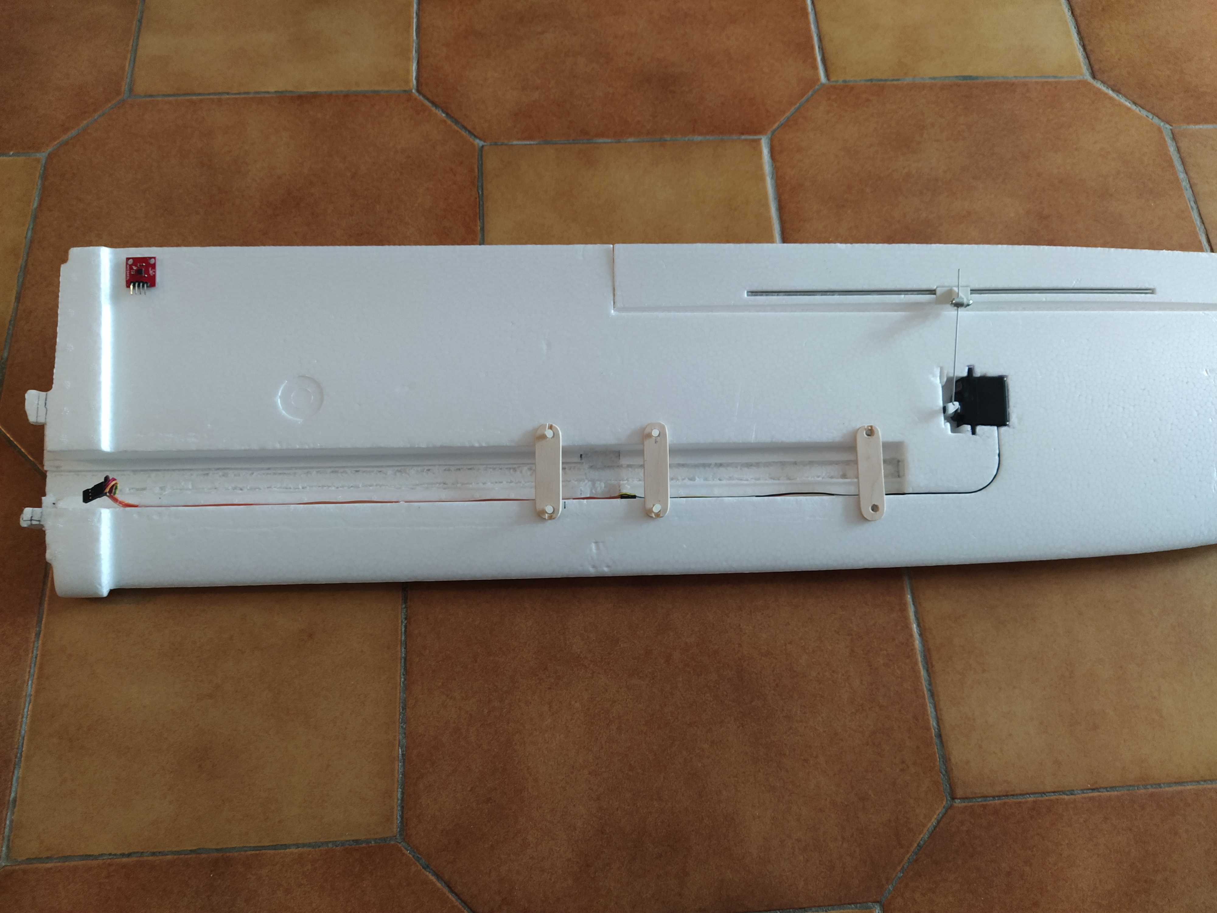
The front part of the fuselage contains, from front to back: battery 1 (placed on a 1mm wood plate, itself glued to the fuselage), the elevator servo, the R/C receiver, the 5.5V converter.
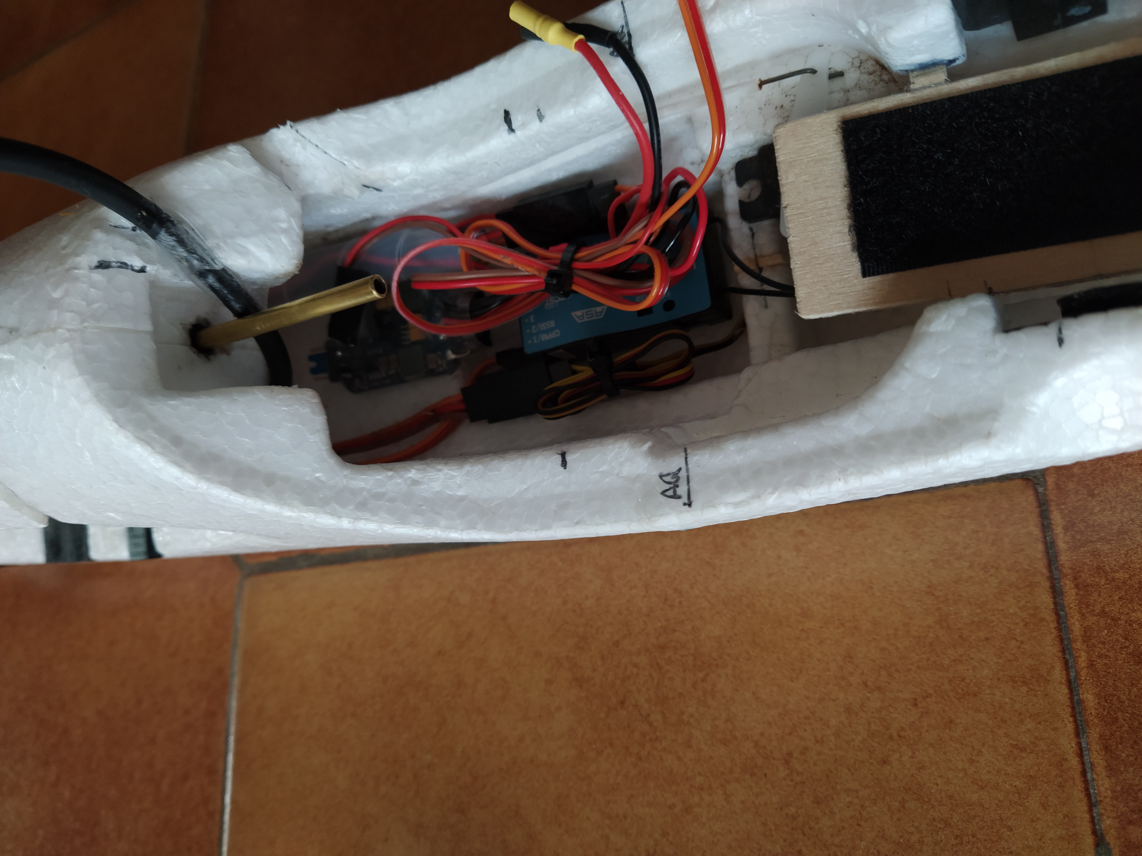
Fig. 3 Equipment in the front part of the fuselage.
Motor locations
Parameters |
Value |
|---|---|
distance between the front motors |
\(635mm\) |
front motor arm length (from leading edge to motor axis in vertical position) |
\(155mm\) |
distance between rear motor and leading edge |
\(520mm\) |
Tilting mechanism
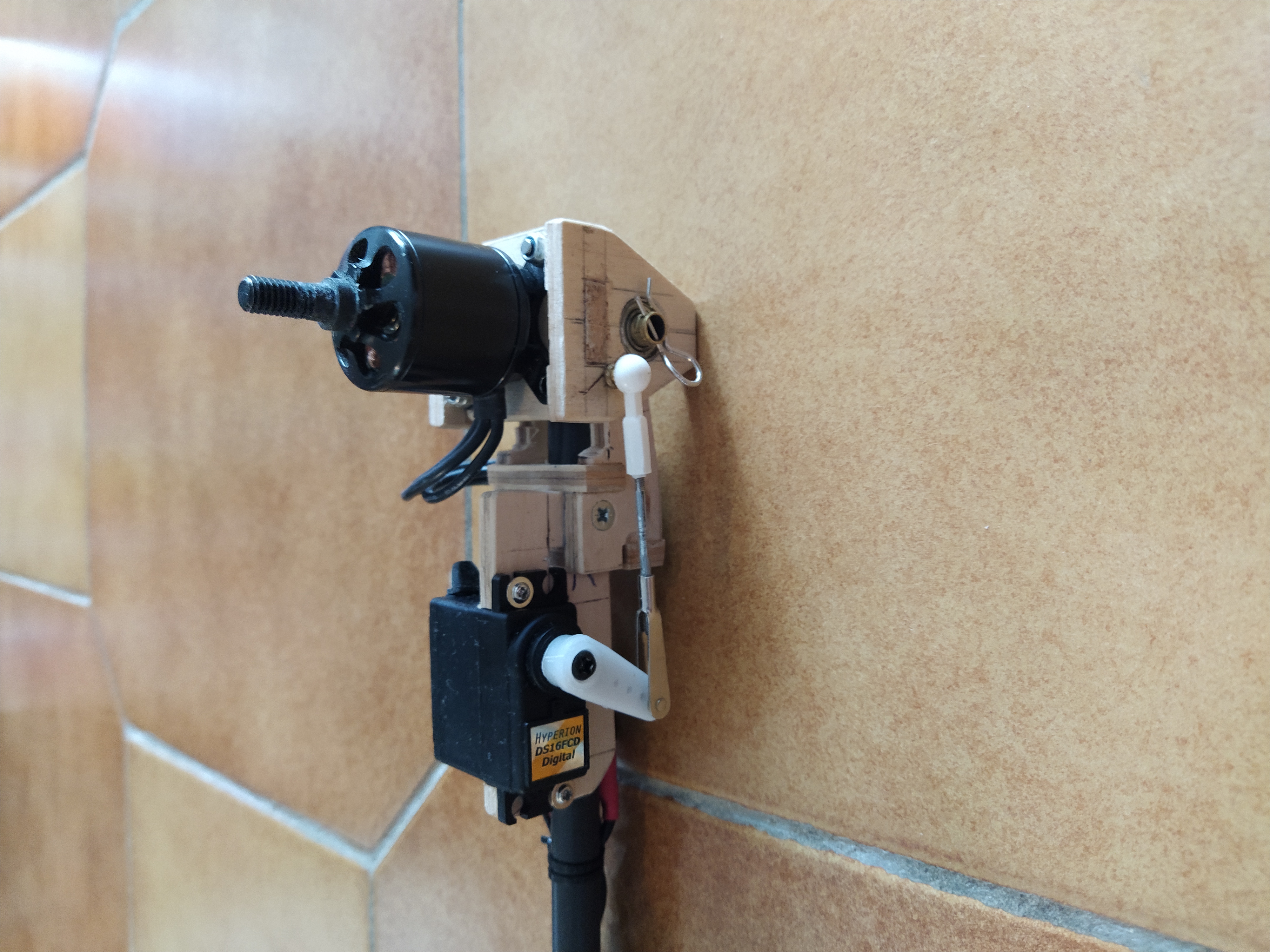
Fig. 4 Tilt rotor mechanism.
The tilting mechanism needs to be accurate for small tilt angles (+/-10° for yaw control), but also rotate by 90° in forward flight. To increase accuracy, the axis is guided with two ball bearings. The tilt actuation is performed with two Hyperion DS16 servos.
Motor arm mounting
The main modification to the original Easyglider is the wing spar. Indeed, for the chosen motor configuration, the spar needs to handle a large effort in hovering due to the the large lever arm between the spar and the front motors. The original plastic tube is replaced with a 14mm section aluminium square tube. 10mm carbon sqaure tubes are glued at each extremity of the aluminim tube to reach the original plastic spar length. Two blocs of hardwood allow to connect the aluminium tube with the motor arms. The motor arms are 10mm carbon tubes.
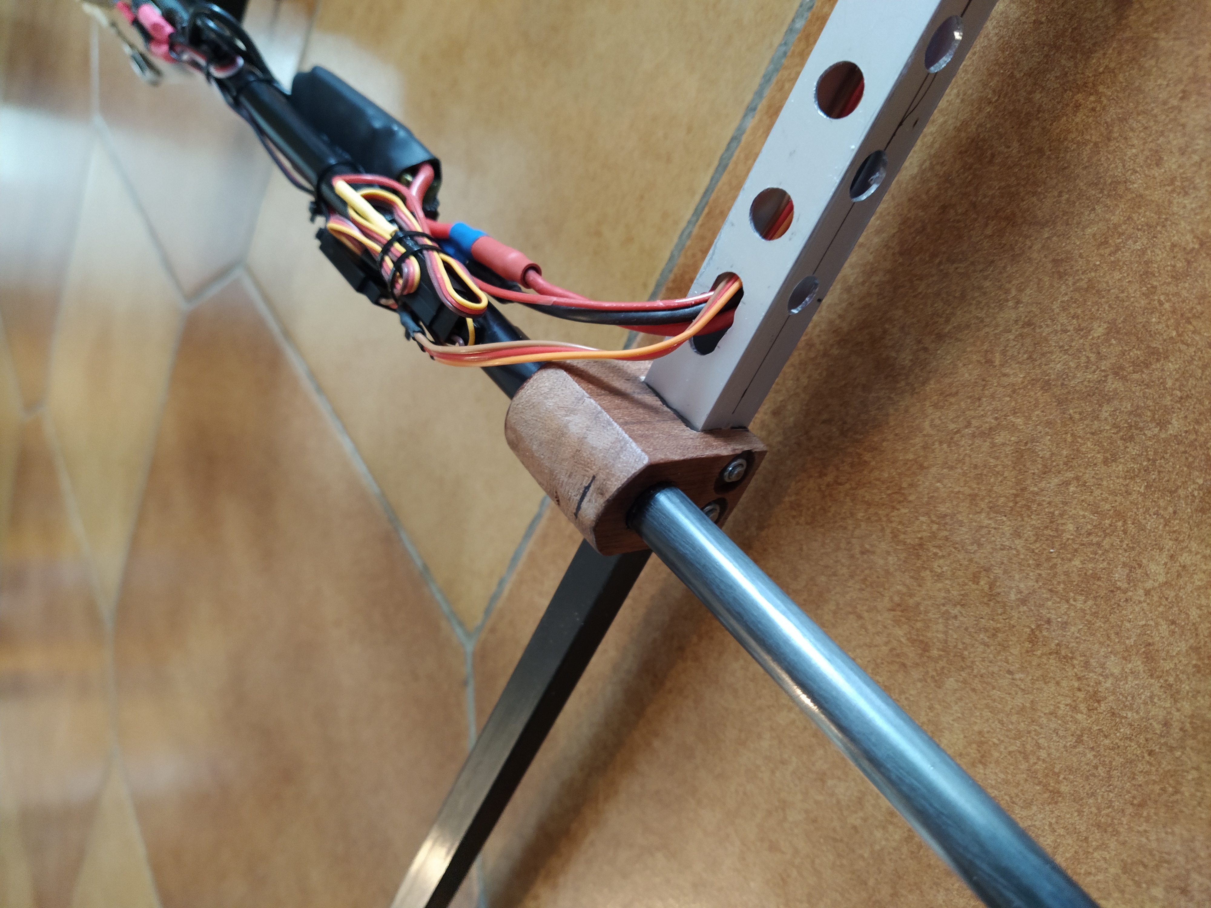
The spar tunnel needs to be enlarged to allow the new aluminium tube to pass. To lock the spar in the wing, 3mm wood plates fixed with 4mm nylon screws are used.
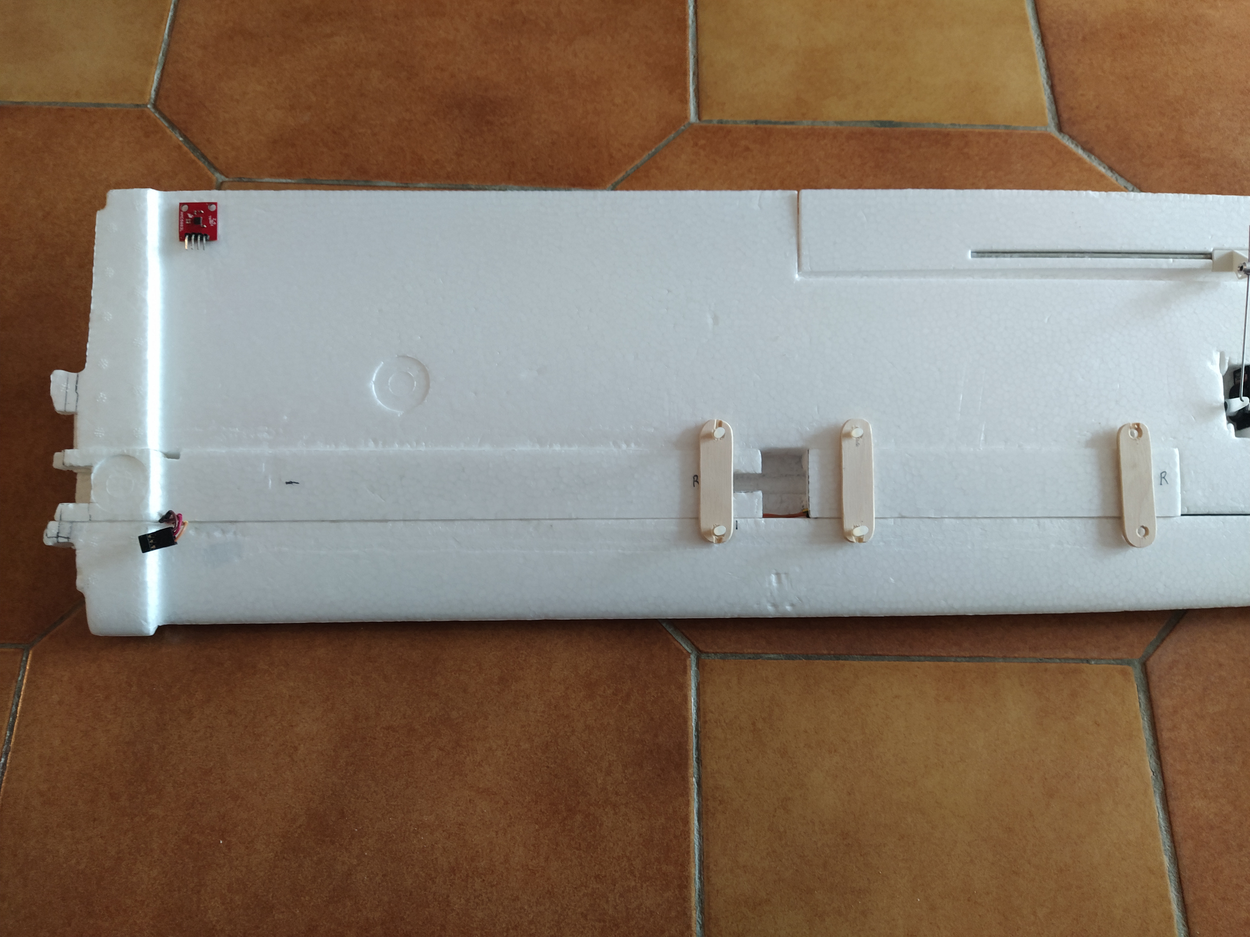
Wing mounting
For the same reason as explained above, the wing mounting needs to handle a large pitching effort. A 10mm threaded shaft is fixed in the aluminium tube. Inside the shaft, a 8mm aluminium tube and a 6mm carbon tube are glued. The wing can be removed from the fuselage. The wing is maintained on the fuselage with a 4mm copper tube. This tube passes through two small 6mm carbon tubes glued in the fuselage at the front and back of the wing.
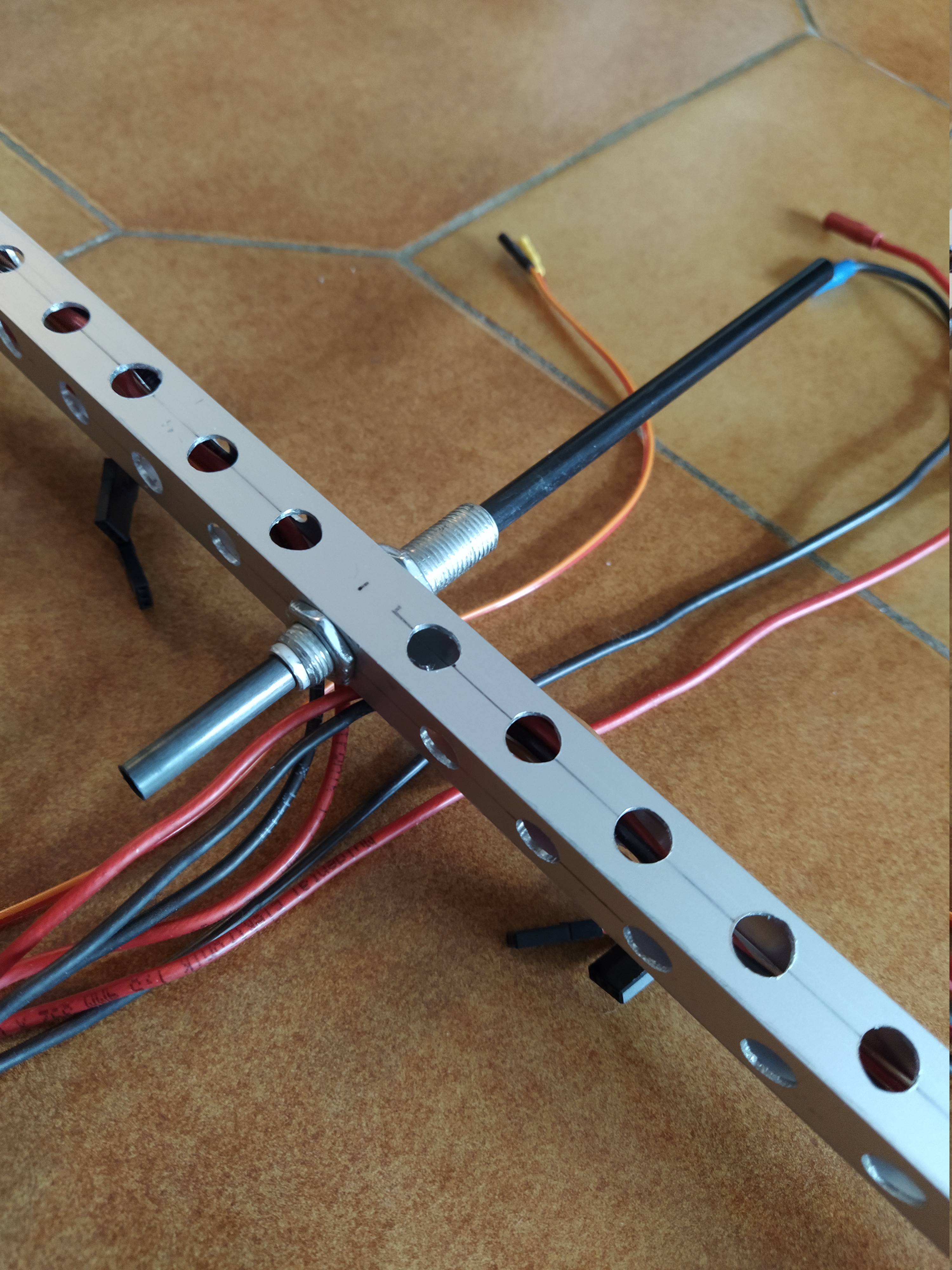
Fig. 5 System used to fix the wing to the fuselage. The wing can be unmounted for easier transport.
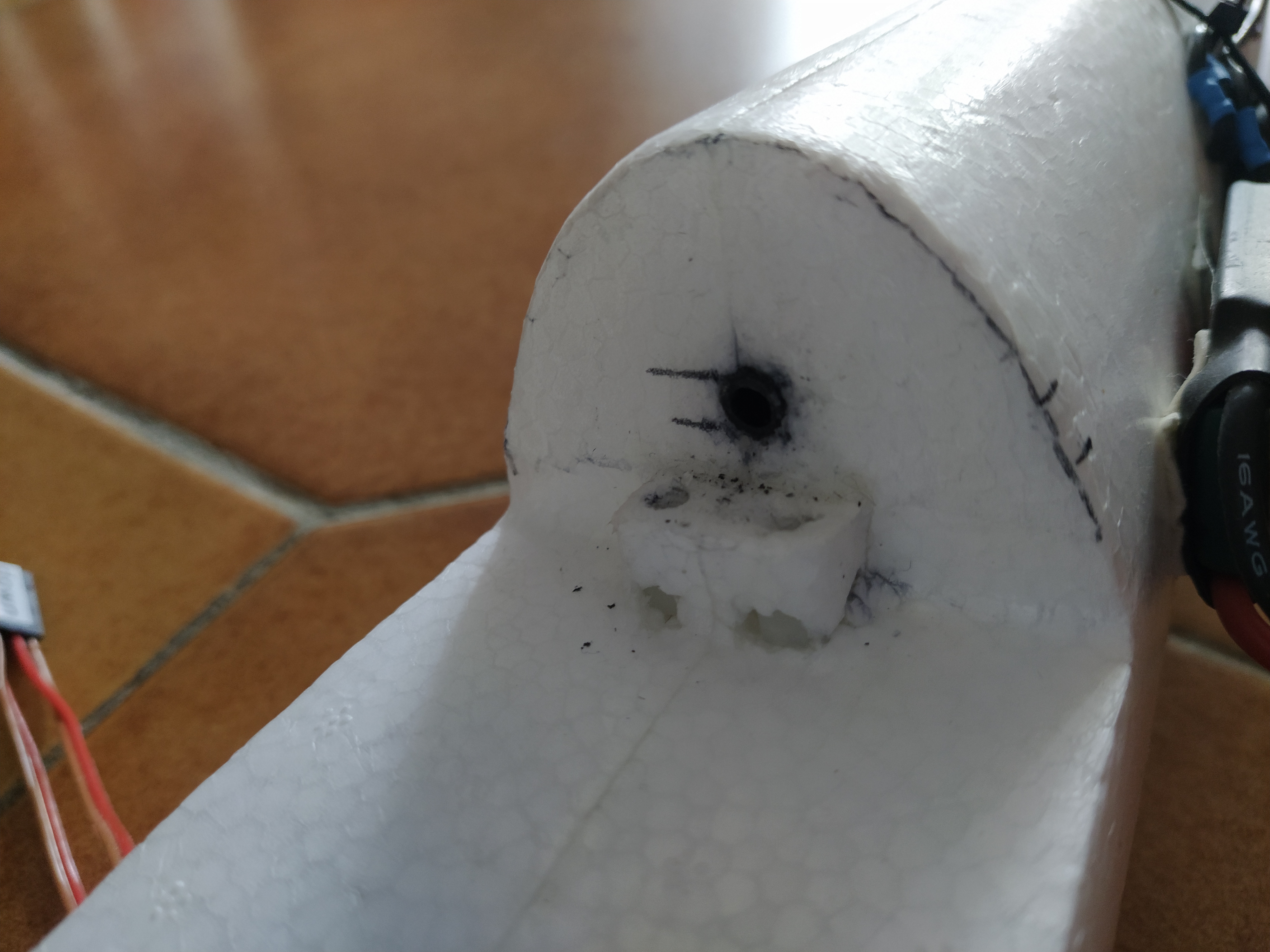
Fig. 6 6mm carbon tube glued on the fuselage at the back of the wing. A similar tube is glued at the front.
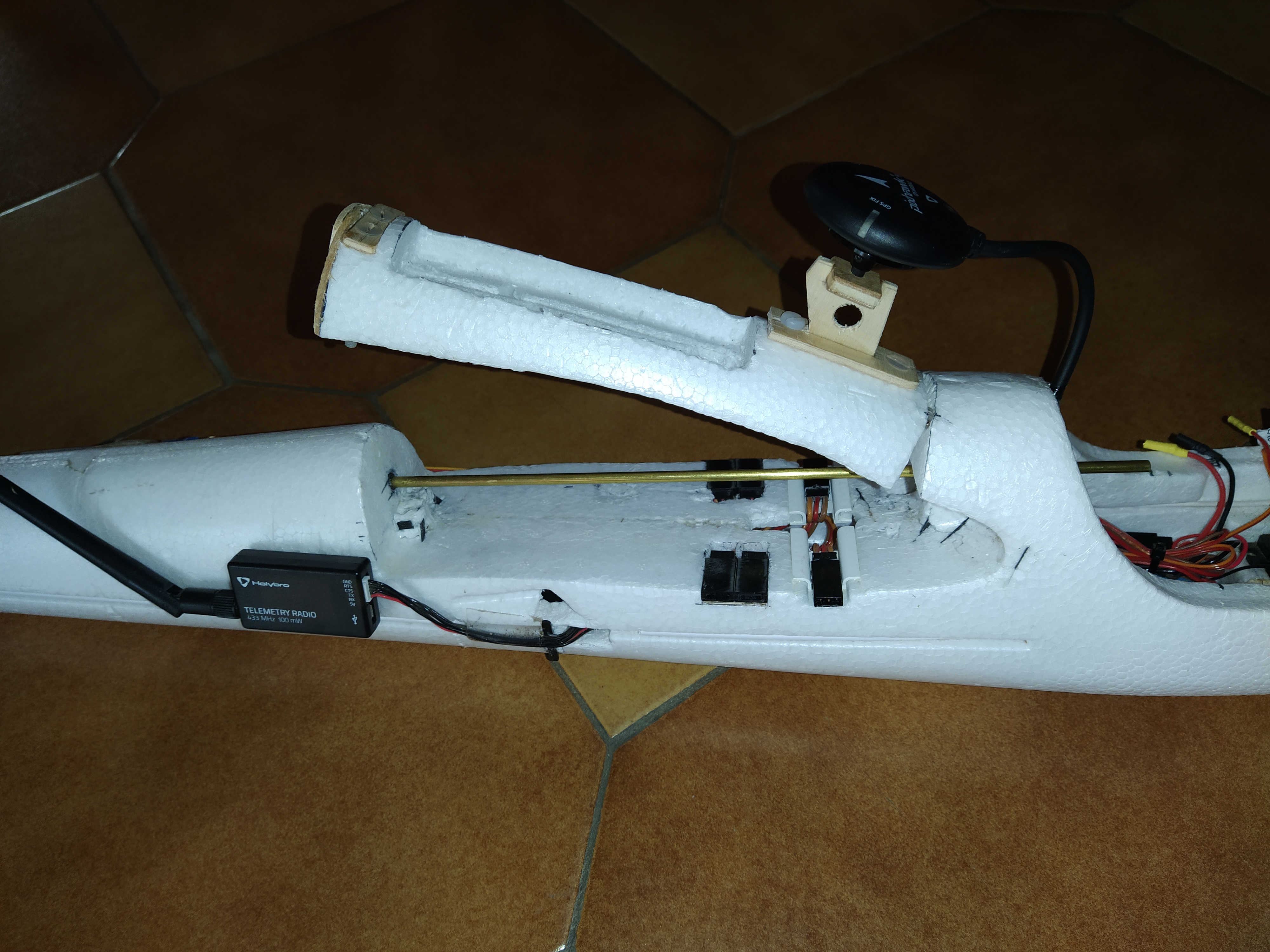
Fig. 7 Wing locking bar, which is a 4mm copper tube.